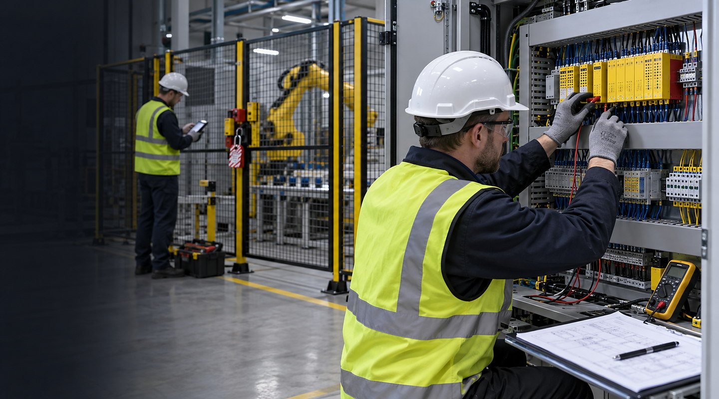
Machine Safety PLCs: How the Process Works
Follow the operating sequence for machine safety PLCs, from preparing the input and controlling the main task to handling exceptions and checking results.
Machine Safety PLCs should be considered as part of a complete production sequence: inputs are prepared, the main task is controlled, exceptions are handled and results are checked.
For your application, the important details include required safety functions and safe states, input devices, zones and operating modes, safety PLC hardware, program and version control, and safe outputs, drives and standard-control interfaces.
Understand the complete route from input to accepted output — Machine Safety PLCs
Plan a machine safety PLC project around defined safety functions, inputs, safe outputs, operating modes, reset and restart behaviour, diagnostics, controlled software and validation evidence. Follow the material or part through each operating step and include recovery, cleaning and change in the real cycle.
Discuss your application

Four clear stages for machine safety PLCs
At each stage, you can review how required safety functions and safe states and drawings, software records and validation evidence affect the next commitment.
- 01
Document Every Existing and Required Safety Function
Share the machine, defined safety functions, drawings and observed stop behaviour, including the normal range for required safety functions and safe states and the difficult input devices, zones and operating modes cases.
- 02
Design the Safety PLC Architecture and Controlled Software
Compare suitable methods and use focused trials to show how each option performs against safety PLC hardware, program and version control.
- 03
Install and Verify Inputs, Logic, Outputs and Interfaces
Connect the equipment to your line, services and controls while resolving safe outputs, drives and standard-control interfaces for day-to-day operation.
- 04
Challenge Faults, Modes, Reset and Restart and Retain Results
Confirm reset, restart, diagnostics and recovery behaviour, then complete and record drawings, software records and validation evidence before your operating team takes over.
Decisions and results stay connected
| Stage | What happens | What you can review |
|---|---|---|
| Document Every Existing and Required Safety Function | Confirm the requirements for machine safety PLC integration, the operating range and the definition of a good result. | Your samples, current information and any points that still need confirming. |
| Design the Safety PLC Architecture and Controlled Software | Compare workable methods using required safety functions and safe states and input devices, zones and operating modes from your real production. | The trial method, observations and reason for the recommended route. |
| Install and Verify Inputs, Logic, Outputs and Interfaces | Resolve safety PLC hardware, program and version control, safe outputs, drives and standard-control interfaces and the physical, control, safety and data connections. | The agreed layout, line connections and any changes from the proposal. |
| Challenge Faults, Modes, Reset and Restart and Retain Results | Check normal, difficult and fault conditions before your team takes over the system. | Results for reset, restart, diagnostics and recovery behaviour and drawings, software records and validation evidence, plus actions and operating information. |
Keep connected responsibilities clear
Your final machine safety PLCs scope must also account for reset, restart, diagnostics and recovery behaviour, drawings, software records and validation evidence, current regulations and the conditions at your site.
- A safety PLC does not make an inadequately defined safety function acceptable.
- Hardware and software changes require controlled versions and validation of the complete function.
- Required risk reduction and final conformity responsibilities remain machine-specific.